

MRQ1 saha arıza rölesi, senkron jeneratörleri uyarma kaybı nedeniyle kararlı çalışma alanı dışında çalışmaya karşı korur. Senkron bir makinede kısmi veya tam uyarma kaybı meydana geldiğinde, reaktif güç sistemden makineye akar ve makine terminallerinden bakıldığında görünen empedans, R-X diyagramındaki negatif X bölgesine gider. MRQ1, düşük veya düşük empedans durumunu algılar ve jeneratör devre kesicisini çalıştırır, böylece adım dışı çalışma ve sistem kararsızlığı nedeniyle hasarı önler. Düşük empedans ölçümü, ayrı empedans ve zaman ayarlarına sahip iki eleman sağlar. Bu nedenle, dinamik ve kararlı durum stabilite eğrisine göre ayarlama mümkündür. MRQ1, jeneratör akımı ve voltajından anlık empedans değerini hesaplar ve bu değeri düşük empedans elemanlarının iki ayarı ile karşılaştırır. Empedans çemberi altında no. 1, jeneratörün kararlı durum stabilite alanını yeniden üretir. Eleman no. 1, alarm amaçlı ve uyarmayı artırma gibi düzeltici önlemler için kullanılabilir. Öğe no. 2 jeneratörün dinamik stabilite alanını yeniden üretir. Zaman gecikmesi daha düşük bir değere ayarlanır. Tam alan kaybında hızlı temizleme sağlar ve 1 numaralı elemanı yedekler. Eleman no. 2, jeneratör devre kesicisini hızlı bir şekilde açmalıdır. Aşağıdaki faktörler iki elemanın ayarını belirler: Jeneratörün stabilite diyagramı, jeneratörün uyarma sistemi ve sistem konfigürasyonu.
FEATURES & FUNCTIONALITY
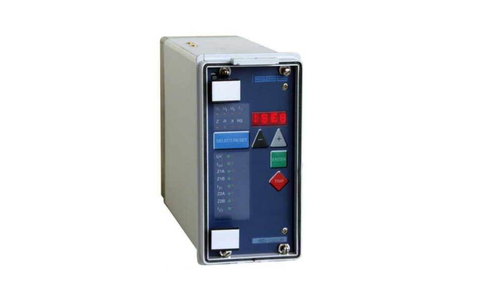
MRQ1 saha arıza rölesi, senkron jeneratörleri uyarma kaybı nedeniyle kararlı çalışma alanı dışında çalışmaya karşı korur. Senkron bir makinede kısmi veya tam uyarma kaybı meydana geldiğinde, reaktif güç sistemden makineye akar ve makine terminallerinden bakıldığında görünen empedans, R-X diyagramındaki negatif X bölgesine gider. MRQ1, düşük veya düşük empedans durumunu algılar ve jeneratör devre kesicisini çalıştırır, böylece adım dışı çalışma ve sistem kararsızlığı nedeniyle hasarı önler. Düşük empedans ölçümü, ayrı empedans ve zaman ayarlarına sahip iki eleman sağlar. Bu nedenle, dinamik ve kararlı durum stabilite eğrisine göre ayarlama mümkündür. MRQ1, jeneratör akımı ve voltajından anlık empedans değerini hesaplar ve bu değeri düşük empedans elemanlarının iki ayarı ile karşılaştırır. Empedans çemberi altında no. 1, jeneratörün kararlı durum stabilite alanını yeniden üretir. Eleman no. 1, alarm amaçlı ve uyarmayı artırma gibi düzeltici önlemler için kullanılabilir. Öğe no. 2 jeneratörün dinamik stabilite alanını yeniden üretir. Zaman gecikmesi daha düşük bir değere ayarlanır. Tam alan kaybında hızlı temizleme sağlar ve 1 numaralı elemanı yedekler. Eleman no. 2, jeneratör devre kesicisini hızlı bir şekilde açmalıdır. Aşağıdaki faktörler iki elemanın ayarını belirler: Jeneratörün stabilite diyagramı, jeneratörün uyarma sistemi ve sistem konfigürasyonu.